


Metal fatigue identification device (in the process of patent application)
1.Summary
This device can capture quantitative subtle changes in electric conductivity and magnetic permeability in high sensitivity, and by a magnetic sensor system that differs from the traditional overflow style sensor system.
2.Characteristics
- The sensor can measure parts of flat sizes with around 30mmφdiameter.
- To measure the fatigue damage value, non-fatigue parts need to be compared; however, in some facilities or institutions, and depending on some devices, there are parts which have almost no stress effect. In this case, it is possible to estimate the fatigue damage value of metal fatigue damaged parts by measuring the comparison value of those parts.
- This device advances metal fatigue, and can measure regularly the parts, which have an anxiety of breaking. It also estimates the progress value of metal fatigue by the change tendency of its numerical value.
- This device is not used for measuring the length or depth of cracks. The purpose of this device is to inspect and manage metal fatigue before destruction occurs by evaluating the measured value tendency, and by monitoring the fatigue parts.
- This device can also capture the change of numerical value in the metal fatigue before crack occurrence.
3.Others
- With MFD102B it is recommended to monitor fatigue parts of facilities, and check their safety regularly by measuring the MFD value (electromagnetic substitution characteristics) regularly at various places in the facilities.
- Using the metal fatigue identification device, we can provide every kind of measure and research analysis on metal fatigue.
This device is a product developed through the guidance and support of the Japan Small and Medium Enterprise Corporation, Kanagawa Industrial Technology Research Institute, and Yokohama National University.
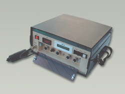
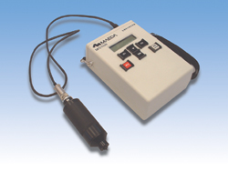
Metal fatigue identification device specifications
| MFD101B | MFD102B | |
 |
 |
|
| Shape | 320mm W×155mm H×320㎜D | 150mm W×190mm H×68mm D |
| Weight | 5.0kg | 0.9kg |
| Power supply | AC100V±10% 50/60Hz | AC100V±10% 50/60Hz or Nickel hydrogen storage battery size AA (1.2V) 6 pieces (charger attached) |
| Usage of frequency band | 50Hz-39.99kHz、10Hz STEP | 50Hz-39.99kHz、10Hz STEP |
| Sensor drive output (sine wave) | Maximum voltage 10Vpeak Maximum electric current 0.5Apeak |
Maximum voltage 0.2Vpeak Maximum electric current 10mApeak |
| Sensor measuring signal input | Ground wire maximum voltage1Vp-p | Ground wire maximum voltage1Vp-p |
| Level adjustment range | 0-±10Vpeak | 0-±0.2Vpeak (Single turn half fixed trimmer) |
Product appearance and specifications may change without notice due to improvements.
This device is a product developed through the guidance and support of the Japan Small and Medium Enterprise Corporation, Kanagawa Industrial Technology Research Institute, and Yokohama National University.
Measuring System for Metal Fatigue Identification Devices
Measuring sensor
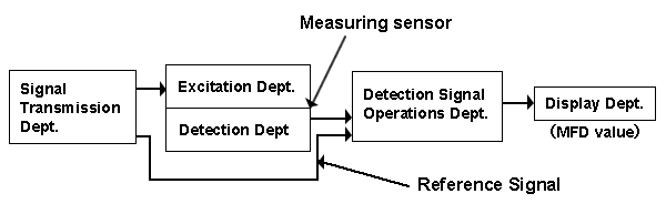
The outline of the measuring system takes place in the Signal Transmission Dept., which drives the excitation coil, and releases reference signals.
The measuring sensor is also composed by the Excitation Dept. and the Detection Dept.
The signal detected by the detector coil includes elements of different amplitudes and phases by the level of fatigue; therefore, it is calculated with the reference signals, and the results are shown digitally to the Display Dept.
The MFD value of the measurement result is an electromagnetic substitution property value that displays the above contents digitally.
This device is a product developed through the guidance and support of the Japan Small and Medium Enterprise Corporation, Kanagawa Industrial Technology Research Institute, and Yokohama National University.
Measurement samples using the metal fatigue identification device
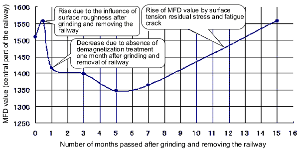
Measurement condition of railroad rails
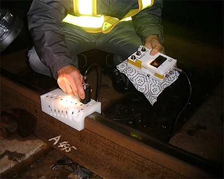
Measurement sample of 60 km railway rolling fatigue
Change of MFD value (electromagnetic substitution characteristic value) by the forged frequency of forged metal mold and fatigue crack occurrence
(Sample of MFD value decrease with the forged frequency of forged metal mold punch for automobiles)
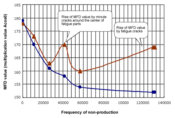
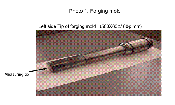
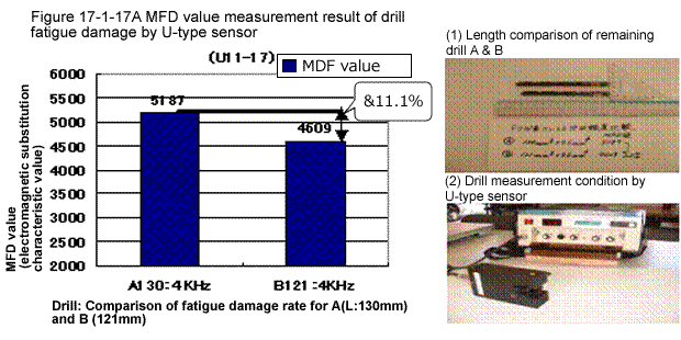
Photo 1: Sample of measure fatigue damage rate by drill abrasion (application example of U-type sensor)
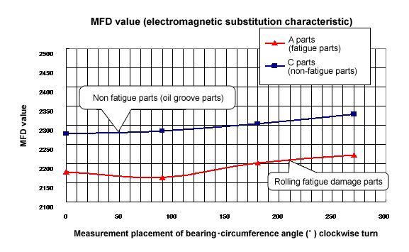
Measurement result of rolling fatigue value for Collo axis bearing
Measurement of rolling fatigue of bearing materials (SUJ2)
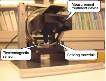
Installation condition of special measurement treatment device for collo axis and magnetic sensor
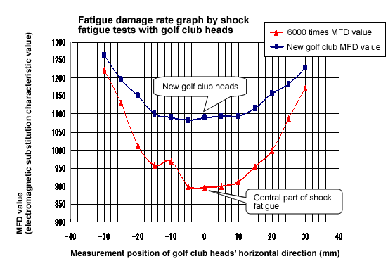
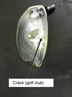
Shock fatigue by golf club heads (Ti alloy)
Fatigue damage rate graph by shock fatigue tests with golf club heads
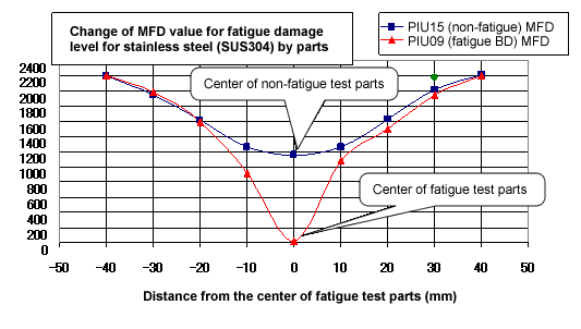
Result of fatigue test for stainless steel (SUS304) (non-magnetic materials)
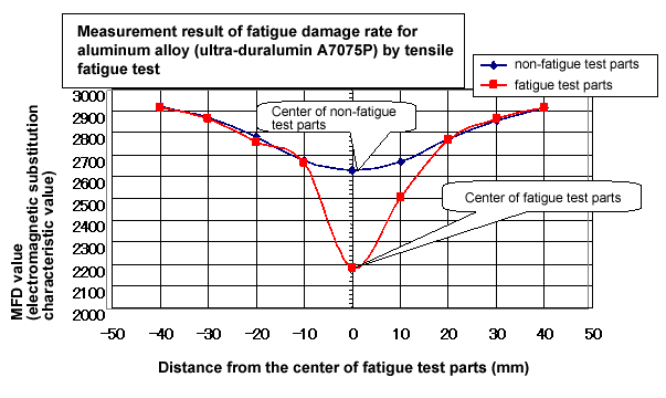
Aluminum alloy (ultra-duralumin A7075)
Measurement result of fatigue damage rate for aluminum alloy (ultra-duralumin A7075P) by tensile fatigue test
Proposal for new maintenance methods adaptable to current situations
Condition-based maintenance system

What is CBM(Condition-Based -Maintenance)?
We conduct conventional detailed inspection regularly once a year for condition-based maintenance using the TMB method through overhaul to acquire the level of fatigue damage,
However, with the CBM method, we can always measure and inspect parts, and detect and handle unusual conditions at an early stage to prevent accidents.
We propose a "predictive maintenance" method by regular inspection, and by using a measurement system through the metal fatigue identification device.
Measures are taken based on several previous damage accident cases to monitor the metal fatigue damage level before fatigue cracks occur.
For this purpose, a regular monitoring system through the predictive maintenance management system is conducted,
This device is a product developed through the guidance and support of the Japan Small and Medium Enterprise Corporation, Kanagawa Industrial Technology Research Institute, and Yokohama National University.
Management system for handling metal fatigue using the metal fatigue identification device
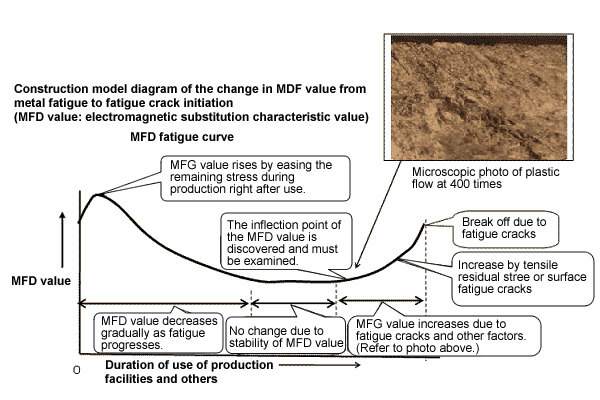
In the case of materials for steel parts, the residual stress is eased in the beginning right after the start of production use, and the MFD value increases slightly, but decreases gradually with metal fatigue though its continuous use.
A period of stability occurs after the MFD value decreases completely, then
rises again in the end by the plastic flow and by fatigue cracks.
The inflection point of the rise of the MFD is discovered, and serves as an alarm of metal fatigue occurrence.
This change in MFD value can be seen in the process of metal fatigue of many parts in many production facilities or institutions.
The installation of a metal fatigue identification device allows such changes to be grasped and predicted accurately in a timely manner.
This device is a product developed through the guidance and support of the Japan Small and Medium Enterprise Corporation, Kanagawa Industrial Technology Research Institute, and Yokohama National University.